Characteristic:1. Valves to meet diverse needs: Our company can provide the valve types shown in the pictures; please select according to your requirements.
2. Standard type: Suitable for applications up to 31.5 MPa (315 kgf/cm²) and (315 bar).
3. Stable operation: The strong attraction of the electromagnet and the spring force of the spool valve make it resistant to dirt, ensuring stable and reliable operation.
4. Special coil for safe use: The fixing nut of the electromagnet has a special loosening design to prevent the coil from falling off due to machine vibration.
5. Excellent waterproof and dustproof electrical installation: Electrical wiring methods include junction boxes and plug-in sockets, both with indicator lights and waterproof and dustproof functions.
6. High quality: 100% functional testing ensures high and stable quality.
7. Simple installation: All valve body fixing bolts are external, facilitating valve body disassembly and assembly. Ample space for electrical wiring makes installation and wiring easy.
8. Mounting surface dimensions conform to ISO4401 standard: Hydraulic transmission - four-way directional valve - mounting surface.
| Technical Parameter |
G02 |
G03 |
| Max Flow (L/min) |
63 |
120 |
| Max Operating Pressure (MPa) |
31.5 |
31.5 |
| Max Allowable Back Pressure (MPa) |
16 |
16 |
| Switching Frequency (Times/min) |
240 |
240 |
| Power Consumption (W) |
AC220V / 50Hz
AC240V / 60Hz
AC110V / 50Hz
AC120V / 60Hz |
Start ≤188Hold ≤60 |
Start ≤366Hold ≤84 |
|
DC24VDC12V |
≤32 |
≤46 |
| ISO Mounting Surface Standard |
|
ISO-4401-AB-03-4-A |
ISO-4401-AC-05-4-A |
| Mounting Screws |
|
Hex Socket ScrewsM5×45, 4 pcs(5–7 Nm) |
Hex Socket ScrewsM6×35, 4 pcs(12–15 Nm) |
| DSG |
-02 |
-2B2 |
-A220 |
-LW |
-19 |
-L |
| Series |
Nominal Size |
Spool Positions & Functions |
Coil Type |
Wiring Method |
Design No. |
Solenoid Reverse Mounting |
| Solenoid Directional Valve Subplate Mounted Type |
02: 6 mm03: 10 mm |
See spool function table for details |
A220: AC 220VA110: AC 110VD12: DC 12VD24: DC 24V |
LW: Standard terminal box typeLWY: Terminal box with connectorL: Standard plug typeNX: Wired plug typeNT: PCB plug typeNY: Clamp type |
19: Hexagonal coil2X: Round coilT: Metal shell coilNM: Nylon sealed coil |
L: Indicated when solenoid is mounted in reverse |
Instructions for Use:
- This product can use the following hydraulic media:
- Petroleum-based hydraulic oil — No. 46 and No. 68 anti-wear hydraulic oil
- Synthetic hydraulic oil — phosphate ester hydraulic oil
- Water-based hydraulic oil — water-glycol hydraulic oil
- Cleanliness management of hydraulic oil:
The presence of contaminants in the hydraulic oil can affect the normal operation of the valve and even reduce its service life. Therefore, the hydraulic oil should be kept as clean as possible (contamination level within NAS 12). It is recommended to use a pipeline filter of 25 μm or finer.
- Oil viscosity and temperature:
The recommended viscosity range is 15–400 mm²/s.
Ambient temperature: -20 to 50°C
Oil temperature range: -20 to 80°C
- Installation orientation is not restricted; however, solenoid directional valves without springs must be installed horizontally.
- The machining surface roughness of the valve mounting surface should be within Ra 6.3, and flatness should be within 0.01 mm.
- The return oil pipe from the hydraulic valve to the tank should be installed below the liquid level of the tank.
- Avoid connecting the return or control drain port of the solenoid directional valve to pipelines that may experience pressure surges. The end of the return pipe should be submerged in oil (it is recommended to fill the return pipe with oil before use) to prevent air from entering.
- For double-coil solenoid directional valves, do not energize both coils simultaneously, as this may cause the coils to burn out.
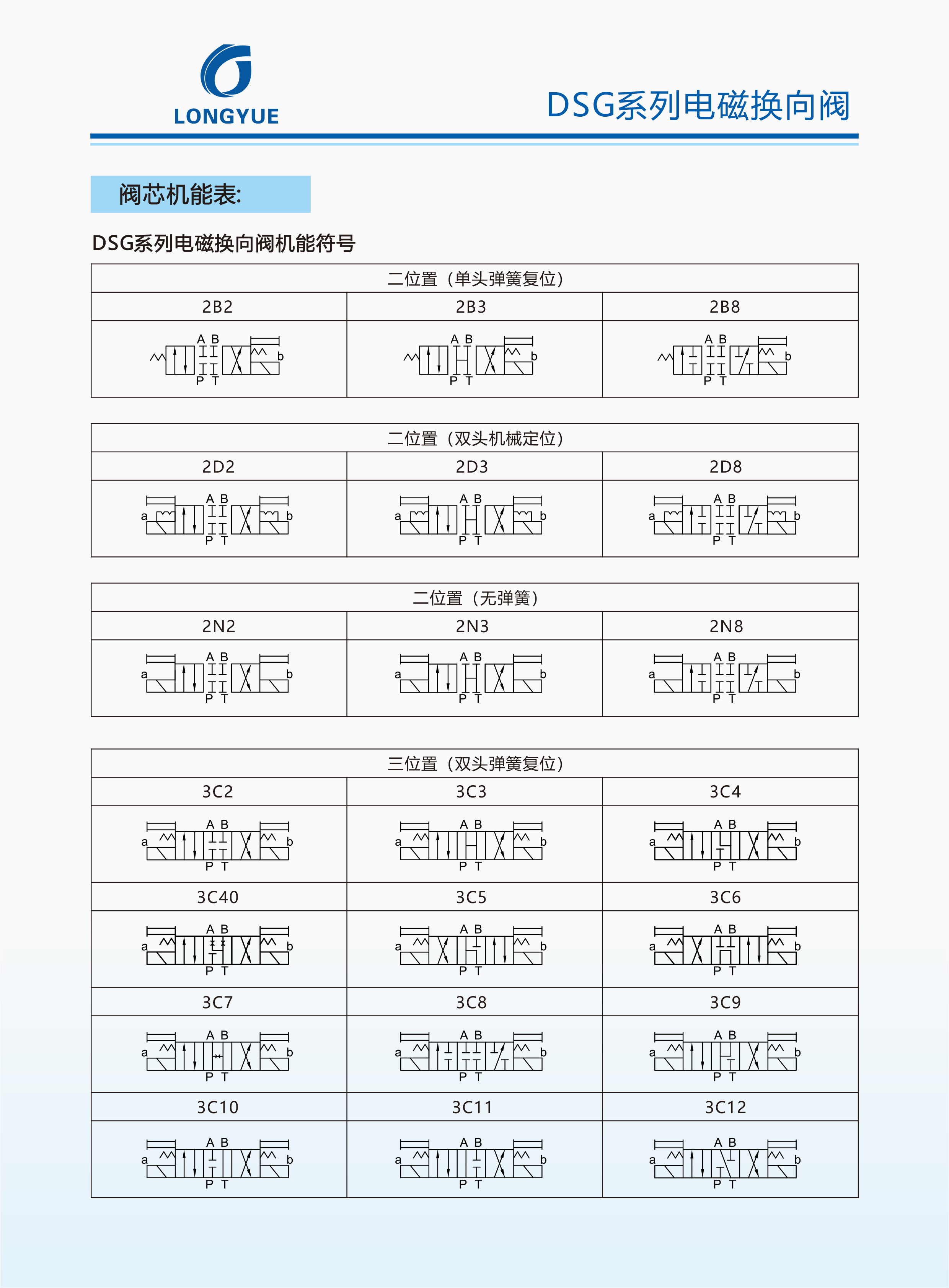
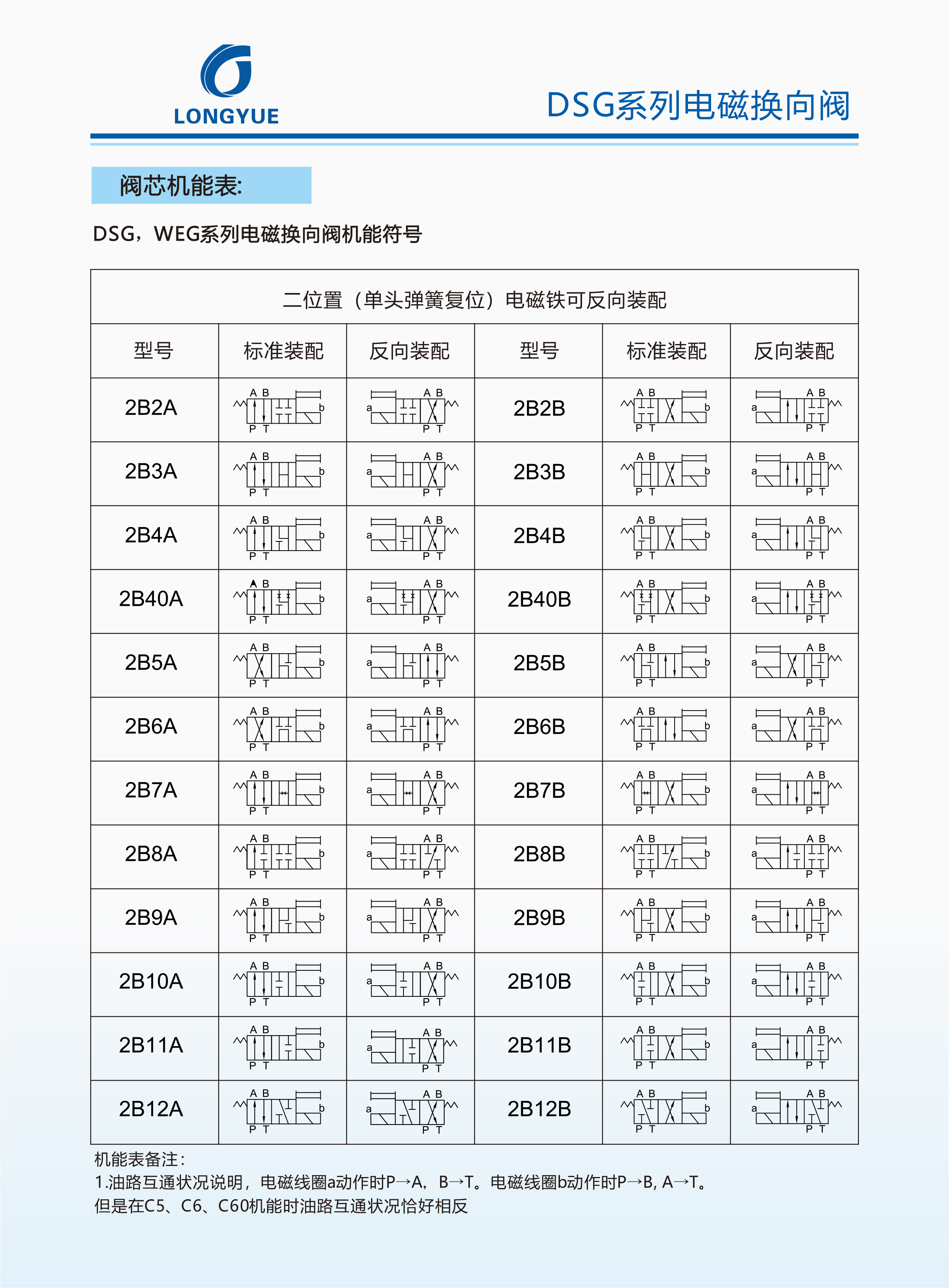 Function Table Notes: Explanation of oil circuit interconnection status: When solenoid coil a is activated, P-A, B-T. When solenoid coil b is activated, P-B, A-T. However, the oil circuit interconnection status is exactly the opposite in functions C5, C6, and C60.


 Function Table Notes: Explanation of oil circuit interconnection status: When solenoid coil a is activated, P-A, B-T. When solenoid coil b is activated, P-B, A-T. However, the oil circuit interconnection status is exactly the opposite in functions C5, C6, and C60.


